Build Partner Reference
COLOR DOME
Architecture & Open Gates — v1.5
The Color Dome is a touring interactive LED exhibit for Museums and Music Festivals where guests use their bodies to create color.
Inside the dome, a LIDAR sensor tracks “PersonStates,” and sends that data to a Python-based runtime stack which translates location to a three-dimensional color wheel — hue, saturation, and brightness.
The resulting color information is sent to the dome’s LED array via sACN-controlled LED output at 30 fps.
This document shares a set of assumptions for the physical build in terms of LED selection, signal processing, and power supply.
Thank you for taking a look!
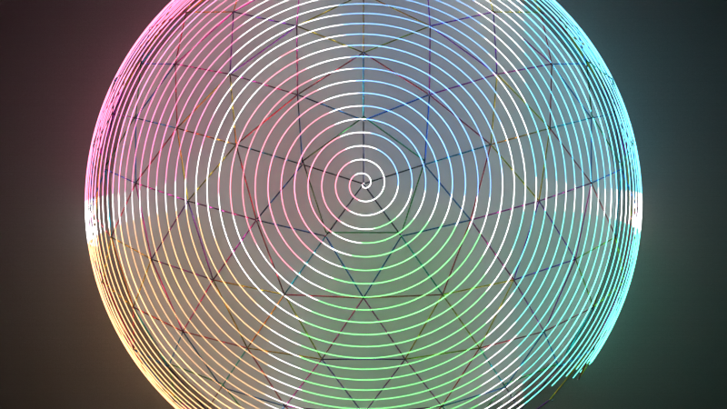
40,330 addressable pixels • 11m diameter • Spiral topology
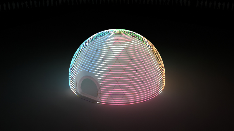
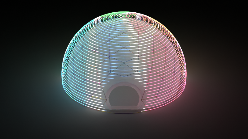
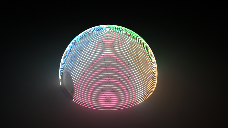
Blender renders — CDRS Preview Master
Locked
ARCHITECTURE FUNDAMENTALS
These elements are committed and stable. Strip family, voltage, channel model, and fixture geometry were bench-locked in June 2026 — see Bench Validation below.
40,330
Addressable pixels
11m
Dome diameter
sACN
E1.31 multicast
30 fps
Default frame rate
- ✓ Distributed DC power (zone-isolated)
- ✓ Software brightness ceiling
- ✓ Managed switch + VLAN + IGMP snooping
- ✓ Advatek PixLite Mk3-class controllers
- ✓ Conservative ~300 px/output planning target
- ✓ Zone-level fault isolation
Bench validated • June 2026
BENCH VALIDATION — STRIP & FIXTURE LOCKED
A bench bring-up on Kurt with a BC-204 controller validated the production strip family, fixture geometry, and 24V power architecture. GS8208 baseline and GS8303 16-bit RGB were tested alongside — GS8304 RGBW carried the win on the strength of 16-bit smoothness plus the dedicated white channel.
Strip
GS8304 RGBW
IC
2904
Color order
WBGR
Channels / pixel
4 (RGBW)
Universes
318
Bench voltage
24V
LED → diffusion
9″ standoff
Strip pitch
12″ vertical
What bench testing told us
- ✓ GS8304 wins on RGBW + 16-bit + thermal. The dedicated white channel justifies the added complexity for the dome.
- ✓ GS8303 is a strong runner-up. “Beautiful… love this strip” — Jon, on the 16-bit RGB. Same fidelity ceiling as GS8304, just without dedicated white.
- ✓ 16-bit family runs cooler at higher LED density. GS8303 at 120 LEDs/m measurably cooler to the touch than GS8208 at 60 LEDs/m. Real thermal advantage for an enclosed-diffusion dome.
- ✓ 9″ diffusion standoff reads as the right blend. Pixels merge into an even wash with no hotspots at 12″ vertical strip pitch.
- ✓ 24V demonstrated. Mean Well LRS-150-24 on the bench. Production architecture follows.
WHY WE PICKED THE GS8304
Color Dome’s strip decision was driven first by visual criteria, then by deployability. The four properties below are why the GS83xx family beat the workhorse alternatives in bench testing.
Highest-priority hardware criteria
- → Smooth gradients
- → Strong low-brightness behavior
- → Minimal visible stepping or banding
- → Minimal camera flicker
- → Stable color and white rendering
- → Voltage flexibility without giving up per-pixel fidelity
Most important differentiator
16-bit color resolution
Materially better than plain 8-bit for:
- • Dim-end smoothness
- • Long gradients
- • Subtle motion in low light
- • Avoiding visible stepping in generative color fields
Directly matches Color Dome’s artistic requirement for smooth, continuous color transitions.
48 kHz PWM
Very high PWM rate is a major advantage for:
- • Filming
- • Slow-motion capture
- • Reducing flicker artifacts
- • Stabilizing low-brightness appearance on camera
The dome will be documented and filmed — flicker defects would be highly visible.
Wide voltage range (3.8V–30V)
Real architecture flexibility — evaluate either:
- • 24V for easier power distribution
- • 12V if required to preserve 1 LED = 1 pixel
…without changing chip family. Exactly the flexibility a 40,330-LED build needs.
Per-color current control
Easier to:
- • Tune color balance
- • Preserve control resolution while lowering output
- • Improve white rendering and channel matching
Valuable when final visual quality matters more than commodity-strip convenience.
GS8304 chosen — GS8303 strong runner-up
GS8304 RGBW • Production pick
Bench testing confirmed the dedicated white channel justifies the added complexity. Higher universe count (318) and additional power demand are acceptable for the dome’s artistic goals.
GS8303 RGB • Drop-in alternate
Same fidelity ceiling without dedicated white. Available as a fallback if GS8304 production sourcing slips.
Both share the same 16-bit / 48 kHz / 3.8V–30V core. Bench notes on GS8303: “beautiful… love this strip.”
Why GS8208 didn’t make the cut
GS8208 was bench-tested as the workhorse baseline. It performs better than commodity 8-bit strips, but the 16-bit family’s smoothness and thermal advantage are visible — especially at higher LED density behind diffusion. Not selected for production. (Bench sample shipped with a dead pixel at index 78, illustrating why field-replaceable strip segments matter.)
Verify
OUR BIG QUESTIONS ABOUT THE GS8303 / GS8304
The preferred GS8303 / GS8304 path is still gated by two production-critical questions about the finished strip product — not just the chip datasheet.
Open evaluation
Is a custom 1 LED = 1 pixel strip worth the cost and power?
Bench testing suggests grouped-pixel GS8304 is acceptable for the dome’s visual goals at our 9″ diffusion standoff. The open question is whether a custom 1:1 GS8304 strip is worth the additional cost and power demands.
Weighing
- • Cost premium of custom 1:1 production runs
- • Power demand increase (more addressable pixels → more current)
- • Visual benefit at 9″ diffusion standoff
- • Sourcing reliability of custom vs off-shelf strip
Working assumption: grouped pixels acceptable. Custom 1:1 strip is an upgrade we’re evaluating, not a blocker.
Production-critical
Does the strip support breakpoint resume / backup data?
Whether the finished product — not the chip-family marketing — actually supports redundant data continuation.
Must confirm
- • Strip supports redundant data continuation
- • Whether a failed LED interrupts downstream pixels
- • Whether breakpoint-resume exists at the strip level, not just chip-family marketing language
At 40,330 pixels, field maintenance risk increases significantly if one failed pixel can disable everything downstream.
Open
OPEN DECISION GATES
Two strategic questions remain open at production scale. The channel-model gate closed during bench validation in June 2026.
Gate 1 — Production-scale Sourcing
Can we source GS8304 RGBW at 40,330-pixel production scale with consistent batches?
Bench validation used a small GS8304 sample. The remaining question is whether ~670 m of dome strip plus 10% spares can be sourced with consistent chip revision, LED binning, and color order.
Gate 2 — Voltage Lock
24V baseline or 48V upgrade?
24V is bench-demonstrated. 48V samples are being sourced — if a 48V GS8304 product is available and the trade-offs check out (see Tradeoff Analysis below), the production voltage may step up.
Gate 3 — Channel Model • Resolved
RGB or RGBW? — RGBW chosen.
Bench testing confirmed the dedicated white channel justifies the added complexity for the dome. Production locks at GS8304 RGBW, 4 channels/pixel, 318 universes.
STRIP PATH
Production pick, drop-in alternate, and retired candidate. Bench-locked June 2026.
Bit depth
16-bit
PWM
48 kHz
Channels
4 (RGBW)
Universes
318
Bench-validated June 2026 (IC 2904, color order WBGR). 48V variant under inquiry as a potential upgrade.
Bit depth
16-bit
PWM
48 kHz
Channels
3 (RGB)
Universes
238
Same 16-bit / 48 kHz fidelity core. Used if GS8304 production sourcing slips. Lower universe count, simpler control path.
Bit depth
8-bit
PWM
8 kHz
Channels
3 (RGB)
Universes
238
Bench-tested and not selected. Lower fidelity ceiling and warmer thermals than the GS83xx family.
POWER ARCHITECTURE
Power planning follows a single rule: engineer from measured sample behavior of the final strip, not from a legacy strip family’s nominal current.
Locked
Design fundamentals
- • Distributed DC power zones
- • Per-zone fusing
- • Zone-level fault isolation
- • Software brightness ceiling
- • Staggered zone power-up sequencing
- • Injection spacing validated against real strip samples
Pending sample validation
Awaiting strip selection
- • Final voltage lock (24V baseline; 48V upgrade under inquiry)
- • Per-meter current draw at production scale
- • Total system wattage
- • Final injection interval
- • Final PSU SKU and zone count
- • Tech rider AC requirements
Production baseline — 24V GS8304
- ✓ Bench-validated (Mean Well LRS-150-24)
- ✓ Lower current vs 12V; fewer injection points
- ✓ Easier cable management for long runs
- ✓ Simpler long-run distribution
PSU candidates at production scale: Mean Well SE-600-24 / UHP-500-24 / HLG-600H-24A.
Upgrade under inquiry — 48V GS8304
- → Lowest per-pixel current of any branch
- → Fewest injection points
- → Lightest cable gauge for touring
- → Pending: sample availability + 48V GS8304 sourcing confirmation
PSU candidates (if locked): Mean Well SE-600-48 / HLG-600H-48A. See Tradeoff Analysis below for full 12V/24V/48V comparison.
CONTROL ARCHITECTURE
Protocol & Network
| Protocol | sACN (E1.31) multicast |
| Universes | 318 (RGBW, locked) |
| Channels per pixel | 4 (RGBW) |
| Pixel IC | 2904 (GS8304) |
| Color order | WBGR |
| Frame rate | 30 fps default |
| Sync | E1.31 universe sync |
| Network | Dedicated VLAN, IGMP snooping |
| Switch capacity | 318+ multicast groups |
| Cabling | Cat6 STP + Neutrik EtherCON |
Controllers
| Class | Advatek PixLite Mk3 family |
| Planning model | PixLite E16-S Mk3 |
| Outputs per unit | 16 SPI |
| Pixels per output | ~300 (conservative) |
| Total controllers | 9 (planning target) |
| Total SPI outputs | 144 |
| Pixel IC support | GS8303, GS8304, GS8208 |
| Config | Web-based, sACN native |
End-to-End Signal Path (Preferred Branch)
Brain Computer (Kurt / production host)
  ↓ dedicated sACN NIC
Managed Switch (VLAN, IGMP snooping, 318+ multicast groups)
  ↓     ↓     ↓     ↓     ↓     ↓     ↓     ↓     ↓
 9 × Advatek PixLite E16-S Mk3 (144 SPI outputs)
  ↓
Short data runs to distributed strip segments
  ↓
GS8304 RGBW (IC 2904, color order WBGR)
24V baseline (bench-validated); 48V upgrade under inquiry
  ↑
Distributed 24V PSUs → zone bus bars → fused injection taps
TRADEOFF ANALYSIS
Strip families
| Factor | GS8303 | GS8304 | GS8208 |
|---|---|---|---|
| Color resolution | 16-bit | 16-bit | 8-bit (12-bit gamma) |
| PWM | 48 kHz | 48 kHz | 8 kHz |
| Channels | RGB | RGBW | RGB |
| Voltage range | 3.8V–30V | 3.8V–30V | 12V |
| Universes @ 40,330 px | 238 | 318 | 238 |
| Visual ceiling | Very high | Very high | Lower |
| Sourcing risk | Higher | Higher | Lower |
| Posture | Preferred | Preferred | Strong fallback |
Voltage: 12V vs 24V vs 48V
| Factor | 12V | 24V | 48V (under inquiry) |
|---|---|---|---|
| Per-pixel current | Highest | Moderate | Lowest |
| Injection points | Highest | Moderate | Fewest |
| Cable gauge | Heaviest | Moderate | Lightest |
| Voltage drop per meter | Highest | Moderate | Lowest |
| Long-run distribution | Hardest | Good | Easiest |
| Pixel grouping | Lower | Moderate | Higher (GS8304 spec range is 3.8V–30V) |
| Safety threshold | Well under SELV | Well under SELV | Approaches 50V SELV ceiling |
| PSU vendor pool | Largest | Large | Smaller (industrial/PoE++) |
| Bench validated | — | Demonstrated (Mean Well LRS-150-24) | Not yet |
| Posture | Fallback | Production baseline | Under inquiry — sample sourcing in progress |
48V inquiry in progress
A 48V variant of GS8304 RGBW would simplify large-scale power distribution at 40,330 pixels. The chip’s documented voltage range (3.8V–30V) means a 48V implementation almost certainly groups multiple physical LEDs per addressable pixel — acceptable for our visual goals (see Our Big Questions above), but we’re sourcing samples to verify the trade-off before committing.
RGBW vs RGB
| Factor | RGBW | RGB |
|---|---|---|
| White quality | Better (dedicated channel) | Mixed white only |
| Control complexity | Higher | Lower |
| Universe count | Higher (318) | Lower (238) |
| Artistic flexibility | Higher | Strong, simpler |
PROCUREMENT & VALIDATION
Priority 1
GS8304 / GS8303 @ 24V
- • 1 LED = 1 pixel
- • 60+ pixels/m
- • Black PCB
- • IP20
- • 1m sample minimum
Priority 2
GS8304 / GS8303 @ 12V
If 24V cannot be sourced cleanly, source the same chip families at 12V with the same density goals.
Priority 3
GS8208 @ 12V
Maintain a fallback sample path: GS8208 RGB, 12V, 1:1 pixel, 60 pixels/m.
Sample validation questions
- Exact chip used
- Exact LEDs/m vs pixels/m
- True 1 LED = 1 pixel behavior?
- Exact strip voltage implementation
- PWM behavior
- Actual power draw per meter
- Cut unit
- Black-PCB availability
- Repeat-order consistency
Top procurement risks
- • Grouped pixels hidden behind high LED density
- • Sample strip not matching production strip
- • Unresolved breakpoint or redundant-data behavior
- • Vendor cannot hold chip revision and LED binning
- • Inability to reorder matching material later
CONNECTORS & CABLING
Connector philosophy is voltage-agnostic. Final cable gauges are sized after voltage and current draw lock to the production strip.
| Connection | Connector | Notes |
|---|---|---|
| AC mains → distro | PowerCON TRUE1 | Locking, IP65, touring-rated |
| AC distro → PSU | PowerCON 20A | Standard touring power |
| DC PSU → zone bus | XT60 / Anderson PP45 | High-current DC, tool-free |
| DC bus → injection | XT30 / JST-SM 2-pin | Low-current DC tap |
| Switch → controller | EtherCON (NE8MX6) | Cat6, rugged, locking |
| Controller → strip | xConnect 3-pin / Ray Wu | Pre-terminated pigtails |
Field serviceability
- • All connections tool-free (push-fit, twist-lock)
- • No soldering in the field
- • Modular pre-wired strip segments
- • Every cable labeled (heat-shrink print)
- • Setup target: hours, not days
- • Touring teardown discipline throughout
SAFETY & COMPLIANCE
Applicable codes
- • NEC Article 518 (Assembly Occupancies)
- • NEC Article 525 (Carnivals, Fairs)
- • NEC Article 590 (Temporary Installations)
- • UL-listed PSUs (Mean Well)
- • Fire-rated cable for all AC wiring
- • Local AHJ approval required per venue
Protection
- • GFCI on all AC circuits
- • Per-zone DC fusing
- • Inline injection-tap fusing
- • Star ground topology (single reference point)
- • Dome frame bonded as equipment ground
- • Staggered zone startup
FAULT TOLERANCE
| Failure | Impact | Mitigation |
|---|---|---|
| Single LED fault | Strip-dependent (validated per branch) | Replace strip segment at next maintenance window |
| PSU fault | One zone affected | Hot-swap from onsite spares |
| Controller fault | ~16 outputs offline (~1/9 of dome) | Hot-swap pre-configured spare |
| Switch fault | Entire dome offline | Spare switch, fast manual swap |
| Brain host fault | Entire dome offline | Backup host with engine pre-installed |
Sightseer Interactive
Questions? jonathan@sightseer.fun
Last updated: 2026-05-07
Document: ColorDome_40k_Power_ArtNet_System_Design.md • v1.5 • 40,330 LEDs